The Problem with Seal Water Systems
Water Management Systems can help mills meet their goals for reliability and conservation.
HEINZ P. BLOCH AND TOM GROVE
A survey of published Corporate Sustainability Reports in the pulp and paper industry shows that the reports prioritize the critical need for water conservation and energy savings. Stated objectives often call for a minimum of 5 percent savings and can be as high as 20 percent when the goal is stretched to 10 years.
One example highlighted in a European Union (EU) Eco-Management and Audit Report details raw water intake for cooling and sealing at 17 million m³ (4.6 billion gallons per annum). With a water reduction goal of 5 percent, the mill at issue is looking for ways to save 230 million gallons of water usage.

A portion of this raw water intake is used to provide cooling and lubrication for mechanical seals and packing on pumps and mixers. Experience shows that each pump application uses a minimum of 1.5 million gallons per year based on 3 gpm. Therefore, if seal water consumption is eliminated on 150 pumps, the typical 5 percent water-saving sustainability goal of approximately 230 million gallons could be achieved with a single initiative. This article asks if it is reasonable to eliminate this consumption without impacting the reliability of rotating equipment—and answers in the affirmative.
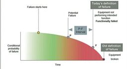
THE API PLANS
Water injected into the pump “stuffing box” is set up to the American Petroleum Institute (API) Piping Plan 32 (Fig. 1). The purpose of water injection is to clear solids from the stuffing box and to lubricate the mechanical seal or packing. This practice, when used on evaporative processes, incurs an additional energy cost. Plan 32 on a Multiple Effect Evaporator with 30 pumps injects 100 gallons per minute that must be reheated and evaporated; this translates to 50,000 MM BTUs (British Thermal Units) and a US$600,000 avoidable annual energy cost.
API Plans 54 or 55 are used on dual mechanical seals in setups that allow water flowing to drain. The water is pumped through a header to multiple pumps and mixers. API Plan 54 means the seal water is at a higher pressure than the process pressure in the seal chamber/stuffing box. API Plan 55 means the seal water is at a lower differential pressure (Fig. 2). The inner seal face set in a dual seal sees seal water as the fluid film on API Plan 54 and it sees the process fluid as the fluid film on API Plan 55. Reliability (uptime) is extended using API Plan 54 when the inner seal faces are lubricated with clean, cool water.
In mills that use API Plans 32, 54 and/or 55, the seal water problem is threefold: 1) poor water quality, 2) inconsistent flow, and 3) inconsistent pressure. Seal water quality standards are cited in the ANSI/HI Rotodynamic Slurry Standard 12.3.8.3.10, which states that filtration will be to “100 percent of 60-µm (0.0024”) or larger particles removed.”

Inconsistent flow is caused when seal water is diverted for area wash-down, by other equipment failures, or during power outages. In API Plan 32, flow velocity must be a minimum of 5 m/s to carry away solids from the average stuffing box; with wider stuffing box bushing clearances the required flow must be increased to achieve this velocity. Industry norm sets the differential pressure for API Plan 54 seal water 15 psig above the seal chamber process pressure. This higher differential is critical on batch or Kamyr digester pumps where the seal water needs to be pressurized to 150 psig or more on a continuous basis. Pulp and paper mill audits confirm that these three minimum standards are seldom universally met; in fact, water can often be observed “gushing” from pump seals.
It can be reasoned that installation of water flow meters will dial back consumption and preserve water. However, flow meters will impact reliability if they clog. Clogging will occur if the seal water filtration standard is not met. Moreover, continuous filtration is expensive and difficult to maintain.
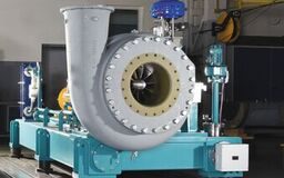
The seal water problem can be solved and seal water consumption eliminated with a Water Management System (Fig. 3). Water Management Systems use in-line filtration to 1-micron, a pressure regulator sets the desired 15 psig differential, and closed loop thermosyphon action cools and lubricates the seal faces. Water replenishment is automatic and does not require operator intervention.
WATER MANAGEMENT SYSTEM CASE STUDY
A US mill upgraded 187 pumps to this Water Management System; this reduced seal water consumption by 400 million gallons per annum. On a demand of 20 million gallons per day, the mill achieves 4 percent of its 5 percent water reduction sustainability goal by converting from the traditional, previously used, water-to-drain piping plan arrangement. Reliability gains come from filtered seal water, correct pressurization, and the self-contained system that is not subject to loss of flow, power outages, or flow diversions.

In essence, plant reliability professionals will consider bridging the distinct operating parameters of slurry-containing processes with existing industry standards for slurry sealing. Their specification addenda will incorporate the reliability- and conservation-enhancing options outlined above.
These proven options will certainly constitute an important amendment to current equipment standards, with payback periods that are surprisingly rapid:
• The mechanical seal must be a dual cartridge mechanical seal suitable for slurry duty and designed to operate at a higher pressure than the process pressure at all times.
• A mechanical seal support system must be provided as a pre-engineered turn-key system; it must include all instrumentation and fittings necessary to install at site.
• The tank capacity must be a minimum of 25 liters (6.6 US gallons) and self-filling. Inner seal face integrity must be visually confirmable at the support system with a flow indicator.
• The system must deliver barrier fluid (seal water) at pressure differentials 15 psig (minimum) above the process pressure in the pump stuffing box at all times.
• The seal system must include localized in-line filtration of plant seal water to 1 micron mounted at the seal pot. An internal standpipe on the supply leg, a 3-way valve on the return leg, and a blow-off valve at the bottom of the tank must be included to allow clearing the system of any contamination after the initial installation and during the life of the application.
• As part of the initial supply package, documentation must include a heat generation report for each installation. The report must refer to the operating conditions for the intended shaft diameter, speed, process/barrier pressure, temperature, and induced flow. The data must provide the input for a thermal equilibrium estimation and result in a calculation of the heat generated by the specific seal supplied in each case.
Coupling this standard to an upgrade strategy is a high-impact, low-cost way to meet sustainability measures of performance (MOP) and to save the precious resources of water and energy. The positive impact to reliability performance and long-term improvement to mean-time-between-failure (MTBF) is achieved when each individual application is correctly pressurized and filtered for fluid film stability.
Heinz P. Bloch, P.E. ([email protected]) is an expert in machine reliability; he has written 20 books and more than 700 articles/conference papers on practical machinery management topics. Tom Grove has spent a career in sealing technology and its application. He is CEO for AESSEAL, Rockford, TN; reach him at [email protected].
Graphics courtesy of AESSEAL Inc., Rockford, TN.