Papermaking Best Practices With Vacuum-Dewatering Systems: Part 1
DOUG SWEET, P.E.
Vacuum systems are essential for papermaking. They contribute to sheet formation and dewatering, press performance, felt conditioning, and general machine efficiency. The vacuum system includes several sub-systems for vacuum control, air/water separation, and vacuum pump seal water management.
 Generally, paper machines operate with little attention required of the vacuum processes. Yet these systems tend to evolve into processes with lost performance. The result is often reduced dewatering capability, which has a direct and negative impact on paper machine efficiency and operating costs. Other problems can include vacuum pump reliability and maintenance problems contributing to downtime.
Observations of almost 1000 paper machines in more than 320 mills in 11 countries have revealed several papermaking facts. These include:
• You can get the sheet to the reel with a poorly performing vacuum system.
• Depth of papermaking knowledge is decreasing in most mills.
• There is often a misunderstanding of how an optimized system is intended to operate.
Application of best practices to significant components and subsystems within the vacuum system will provide discovery of problems and inefficiencies, and will lead to optimization.
A useful list of best practices tends to fall into two categories: process and management. Process best practices are technical; calculations and equipment modifications may be necessary to provide recommendations for optimization. Management best practices are related to personnel, mill procedures and culture, and employee expectations. The best processes may not be well-managed, while the best management may provide superior operation of older processes.
In Part 1 of this two-part series, we’ll look at process best practices. While this article is not intended to be an exhaustive discussion, we’ll cover many details that mills will find helpful.
SHEET FORMATION AND TABLE DEWATERING
Problems are often discovered in low, medium, and high vacuum dewatering elements on all types of formers. These are noted as problems on 90 percent of systems studied and include:
• Lack of understanding of how these systems are intended to operate
• Lack of accurate vacuum measurement and control
• Lack of analysis of data presented in drainage studies
• Effect of poor operation and obsolete vacuum elements on sheet quality, table drive load, and forming fabric life
Early vacuum table operation, formation, and sheet quality are related. Many fourdriniers are found to have uncontrolled and aggressive dewatering occurring at the initial one or two low vacuum elements. Sometimes this can be  observed where vacuum piping is pulsing at a vacuum element, or significant whitewater is seen flowing from small separators at one or more elements. These findings are quickly confirmed with a table drainage study. It is not unusual to find that one low vacuum element is unknowingly removing 10-30 percent of the total headbox flow.
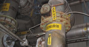
Two common problems found with these systems are lack of vacuum measurement and control, and exceeding physical vacuum or hydraulic limits of early vacuum elements. Many paper machines have evolved poorly where vacuum gauges, manometers, transmitters, and valves are no longer functioning (Fig. 1.) Eventually, failure of these components leads to all low-vac elements being manually operated with most or all valves fully open. This applies full header vacuum to every element connected to the header.
Where good formation requires gradual dewatering to develop the sheet, failure to control early vacuum elements creates aggressive dewatering. Besides contributing to formation problems, sheet sealing can occur and influence dewatering down the table.
 To easily determine maximum vacuum level for any low vacuum element, measure the elevation of the vacuum outlet above the seal pot whitewater overflow. It can be as little as 12” to as much as 40”. Figure 2 shows how this limit is determined.
For evidence of exceeding maximum vacuum of a low vacuum element, observe the back side of the table, where small separator drop legs may have seal tanks, and not just dump into the wire pit. Whitewater can be seen flowing into these tanks. These low vacuum elements should be operating without any whitewater flowing through the vacuum outlet. Significant whitewater passing through the vacuum outlet creates vacuum fluctuations and can cause CD and MD dewatering variations.
Higher vacuum dewatering is applied near the wet/dry line, after formation is complete. Often there are too many flatboxes and/or too much slot area (Fig. 3). Generally, flatboxes do not need more than five or six slots and slot widths are usually decreased as the sheet approaches the couch.
Besides improved dewatering with fewer flatboxes, less slot area, and higher vacuum, efforts usually include reducing table drive horsepower. Reworked flatbox covers using modern low drag ceramics, such as silicon nitride, will add further to reductions in table drive horsepower. This can easily lead to 10-20 percent power being saved among couch, wire turning roll, and other former drives.
Best practices for the table vacuum system include:
• Maintaining accurate vacuum measurement and control for every element
• Understanding how the early vacuum table should be set up
• Observing physical maximum limits for vacuum levels of all vacuum elements
• Vacuum-dewatering optimization efforts
• Eliminating unneeded flatboxes and those with excessive slot area
• Considering low drag/friction ceramics such as silicon nitride
UHLE BOXES AND MEASUREMENT OF UHLE BOX FLOWS
Uhle boxes are essential for efficient press operation, but issues are often found with excessive slot area, resulting in decreased dewatering capability. This is noted as a problem on 50 percent of systems studied. Impact on papermaking can include:
• Reduced uhle box dewatering rates
• Felt shedding and damage
• Limited press exit solids
Uhle box design is pretty simple. TAPPI TIP 0404-27 describes details critical to uhle box design and application. Slot area is based only on machine speed. For example, a total slot width of 1” is required for a machine speed of 2500 fpm. There is no benefit in having additional dwell time because this only adds to vacuum pump capacity and power requirements.
Slot width yields a slot area that is multiplied by a vacuum factor to provide a necessary vacuum airflow per uhle box. This vacuum airflow is used to size the uhle box, piping, separator, and vacuum source. A vacuum factor range is 15-20 cubic feet per minute, per square inch of slot area (cfm/in ). For example, a 250”-wide, 2500 fpm machine with 1” of total slot width will require 4000-5000 cfm per uhle box.
There is no practical reason to have different uhle box designs and slot configurations within the same press, unless only a portion of the press was upgraded. The only decision is whether to have one or two uhle boxes per felt. Two uhle boxes per felt is usually applied where felt cleaning is needed, and not for additional felt dewatering. An existing press with two uhle boxes on a third press felt can often have one of two uhle boxes removed.
Measurement of press fabric water permeability and moisture scans can help determine cleaning and conditioning effectiveness. Generally, if felts are not filled at the end of their life, then single uhle boxes are adequate.
Herringbone or zig-zag uhle box covers are seldom needed when using seamed felts. Seam designs have improved greatly since their introduction in the 1990s. There are many 4000+ fpm machines running six and seven weeks on seamed felts with slotted covers.
Another tool essential to press optimization is measurement of uhle box and press nip flows. This feature exists on the best-running paper machines in the world. Note that this is not limited to the newest machines, because the capability is easily and economically added.
The easiest flow measurement method is using existing seal tanks having V-notch weirs and fitting these with level transmitters whose data can be calibrated to provide flow rates (Fig. 4). Each felt should have its own weir and flow rate value.
The ability to measure and trend all press water removal, and being able to classify where the water came from (uhle boxes or nips), provides valuable data for press
optimization. Mills can then make informed decisions regarding felt design, roll cover materials and designs, chemical cleaning of felts, and managing nip dewatering.
Best practices for felt conditioning and dewatering include:
• Minimize uhle box slots to not exceed 2 milliseconds of dwell time per uhle box
• Verify herringbone (if used) slot areas are not excessive
• Maintain vacuum factors of 15 – 20 cfm/in
• Measure and trend uhle box and nip weir flows
• Combine optimized fabric conditioning and dewatering with analysis of water removal rates to maximize press water removal performance using informed chemical cleaning programs, felt designs, and roll cover design choices.
VACUUM PUMP SEAL WATER SYSTEMS
Vacuum pump seal water is generally ignored until significant problems are causing vacuum issues. Problems associated with seal water systems can include:
• Lack of understanding of how these systems are intended to operate
• Little or no instrumentation for control of seal water flow or pressure
• Little or no monitoring of recirculated seal water quality
• Poor condition of cooling tower
Operation of liquid ring vacuum pumps is relatively simple. The pumps operate at a relatively low speed range, and seal water must continuously be flowing through the pumps. Control of water flow should be made as simple as possible. Each pump model has a standard seal water flow requirement. Too little water decreases pump performance; too much water adds to pump horsepower. The standard rate can vary by plus or minus 10-20 percent with little impact on performance. Therefore, precise flow control is unnecessary. Generally, water flow is controlled with spray nozzles and orifices selected for a specific supply pressure to deliver the correct flow rate.
New vacuum systems are usually installed with all of these features, but can evolve into poorly regulated systems with no pressure measurement, missing orifices, or deteriorating and/or plugged water piping.
Mills allowing clean seal water for these systems usually require little or no vacuum pump maintenance or overhauls. Systems recirculating seal water through cooling towers are usually in the worst shape, requiring frequent pump rebuilds. Basic components are needed regardless of using once-through or recirculated water systems. Seal water headers can be controlled to a reasonable pressure, then throttled at the vacuum pumps.
Orifice sizes and spray nozzles should be verified with the pump manufacturer to deliver correct flows (Fig. 5). Local pressure gauges are necessary to allow adjustments. No elaborate flow meters or other controls are required, although considering lack of instrumentation and/or process knowledge, color-coded seal water gauges are helpful (Fig. 6.)
These systems get messy when cooling towers are introduced. Most vacuum systems installed in the past 25 years have included cooling towers to provide reasonable seal water temperatures without continuous fresh water and sewer requirements. Where cooling towers have been used, problems have included:
• Incorrect tower fill
• Lack of working separators
• Undersized separators
• Separator extraction pump issues
• Overloaded water filters due to excessive water contamination (because of separator issues)
Often, no one seems to have process ownership of these cooling tower systems. They are outside of the machine room so are not within the usual path of operators on routine rounds, and problems are usually not noticed until they become serious.
Best practices with seal water systems include the following:
• Awareness of basic seal water process and flow requirements
• Use of orifices and spray nozzles with pressure measurement and control, or some means of flow measurement for each pump
• Working local pressure gauges
• Understanding the necessity for separators and working extraction pump systems
• Daily or at least weekly inspection of cooling tower
• Simple seal water analysis (pH, conductivity, turbidity) and looking for changes
EXCESS VACUUM CAPACITY
Yes, paper machines often have excess vacuum capacity. There are often opportunities to lower vacuum system operating power by 10-20 percent through analysis and optimization.
Inbleed valves that never close or with high setpoints provide potential for reducing vacuum system horsepower. Other opportunities include elimination of press suction rolls (typically found on older containerboard machines and pulp dryers), and unnecessary flatboxes and uhle boxes as described earlier.
Finding maximum opportunities requires an in-depth study of the system. The greatest improvement this author uncovered was on a 360” printing paper machine that was able to remove 1.2 megawatts from the vacuum system—a 40 percent horsepower reduction.
Best practices for minimizing necessary vacuum capacity and operating power include the following:
• Investigate operation with open vacuum inbleed valves
• Conduct detailed vacuum-dewatering analysis and system audit
• Remove unneeded flatboxes and uhle boxes
• Eliminate press suction rolls where possible —generally, working with roll cover shops and fabric suppliers helps accomplish this
• Monitor vacuum pump motor loads and investigate changes, up and down
Paper machine vacuum systems are an important process for paper machines. Yet, since these systems generally require less maintenance and attention, they become less understood. The ideas presented here should be useful to paper production and maintenance personnel. Applications of these best practices often will require little cost, but benefits will always be measurable.
Doug Sweet, P.E. is principal of Doug Sweet & Associates, Inc., and has more than 40 years of experience with vacuum system optimization in mills around the world. Contact him at
[email protected] and visit www.dougsweet.net.
Fig. 1: Example of poor low-vac control with by-pass valves attempting to control these elements. Note the inoperable valve at the top.
Fig. 2: Determining maximum vacuum level for any low vacuum element.
Fig. 3: Flatboxes with excessive quantities of slots.
Fig. 4: Typical seal tank with weirs; can easily be modified with addition of level transmitter.
Fig. 5: Seal water orifice union—note s/s tab.
Fig. 6: Considering lack of instrumentation and/or process knowledge, color-coded seal water gauges are helpful.